-
Product production process
Product descriptions from the supplier
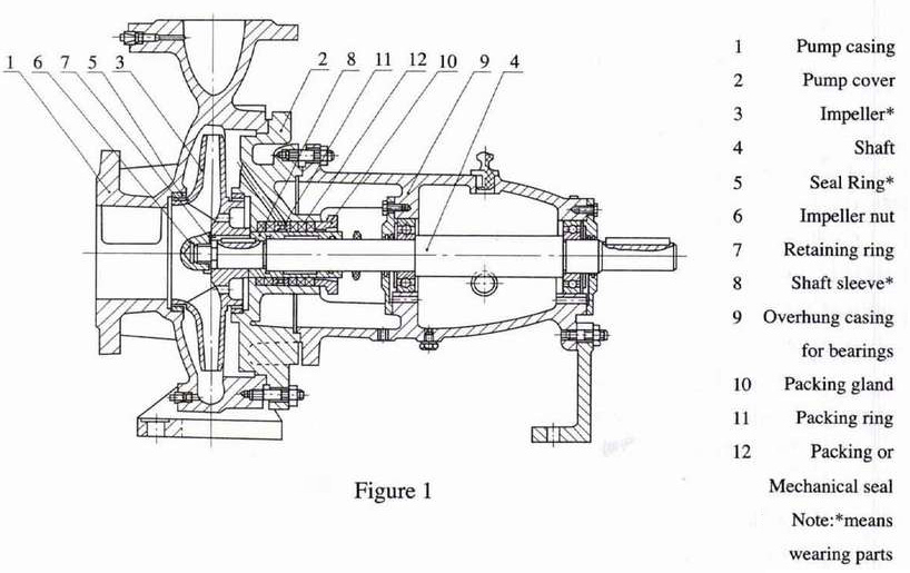
Simply, it is after with drawl of the rotor assembly that it can be done.The pump casing (including the cover) constitutes the working chamber of the pump, while the rotor assembly is composed ofimpeller, shaft and roller bearings. The bearings withstand both redial and axial forces from the pump
For most of the pumps, the purpose of the seal rings provided in both frond and back sections of impellers, and holes-called balancingholes drilled in the back covers of impellers is to balance the axial forces from pumps. Those which do not give too much axial forceshave neither seal rings nor balancing holes in the back section of impellers.
-
Product Features
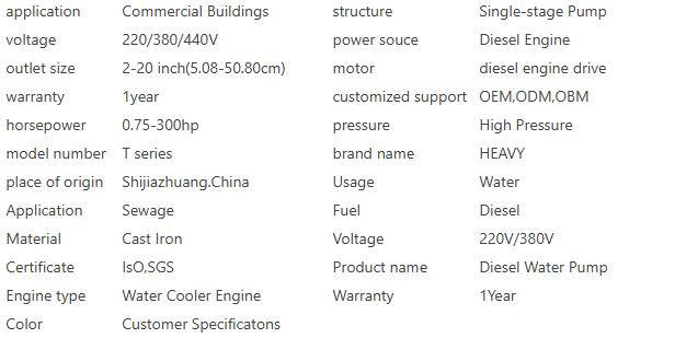
Key attributes
Ratings & Reviews

IR' axial seal is either packing seal or mechanical seal to prevent air from coming or too much water leakage. The pump cover isprovided with internal and external sealing liquid holes as well as cooling chamber which has seal rings to prevent cooling water coming
out. Details as per Figure 1.1. The sealing and cooling methods are:
1) Packing seal, internal sealing liquid, not being connected with cooling water.
2) Packing seal, internal sealing liquid, being connected with cooling water.
3) Packing seal, external sealing liquid, not being connected with cooling water.
4) Packing seal, external sealing liquid, being connected with cooling water.
5) Mechanical seal, extemal sealing liquid, not being connected with cooling water. (without the internal sealing liquid holes dtilled
when mechanical seals are used)
6) Mechanical seal, external sealing liquid, being connected with cooling water. (without the internal sealing liquid holes dtilled
when mechanical seals are used)
Customers will select the sealing and quenching methods listed below according to the application requirements.
Pressure of cooling water P0.15-0.3 MPa. The required amount of sealing liquid is 0.2-0.Sm /h; the amount of cooling circulationliquid is 0.3-0.7m'/h. Customers will decide the liquid amount with reference to above-said values.
To minimize the wear of shafi, the shat uses a sleeve on the point which is go though the packing box. The shaft sleeve is fixed witha O ring to prevent both air and water coming along the mating surfaces.
Pumps are driven from flexible coupling connected motors. The pump rotates clockwise when viewed, standing at the driver end and
facing the pump.For the pump dimensions, refer to Figure 2 and Table 2: the Figure 3 and Table 3 for the details of both suction and discharge flangesand their connection dimensions.
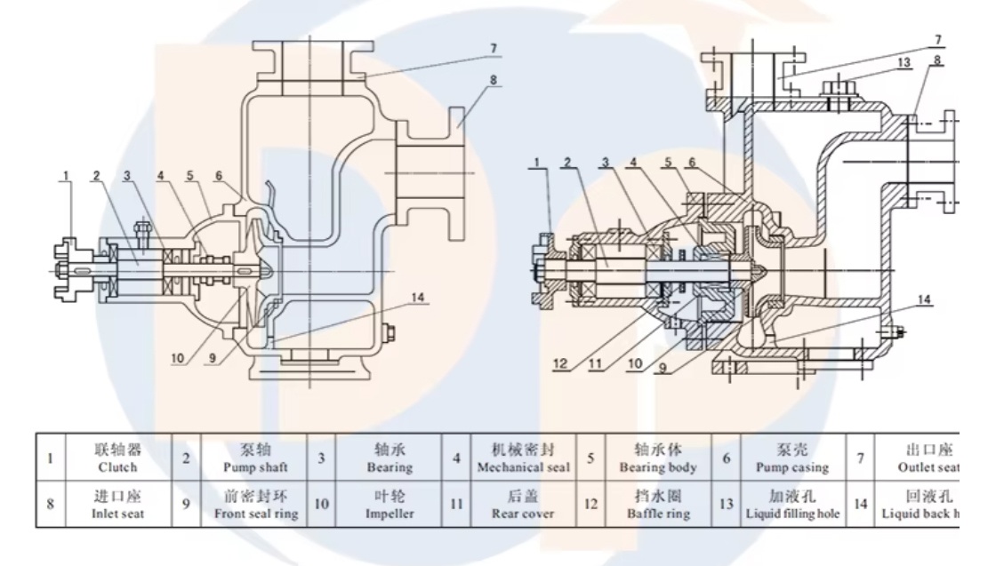
structure chart
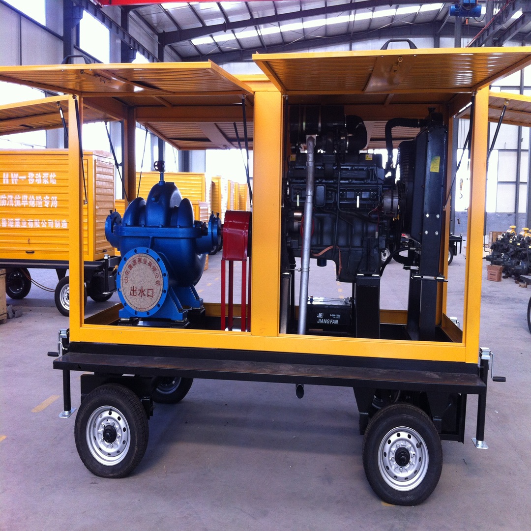
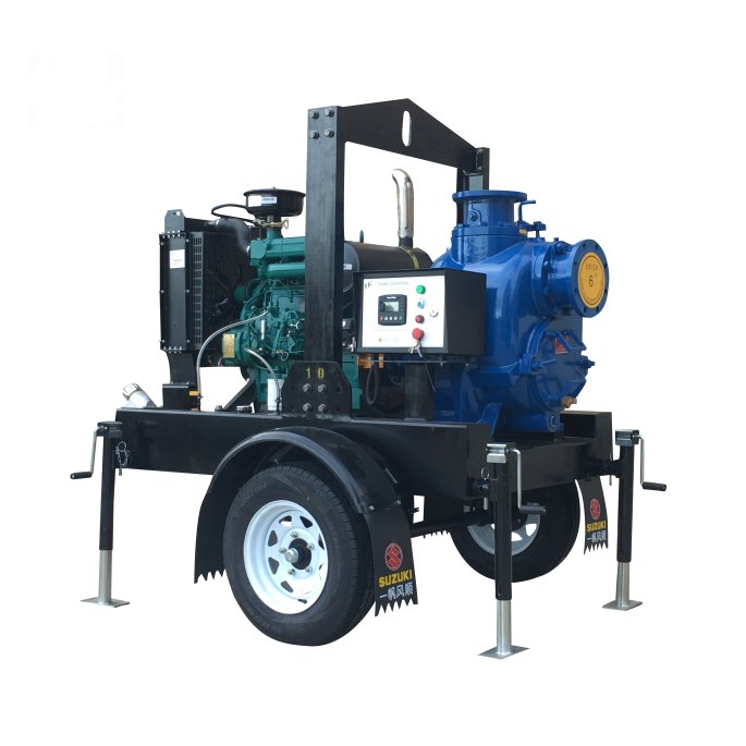
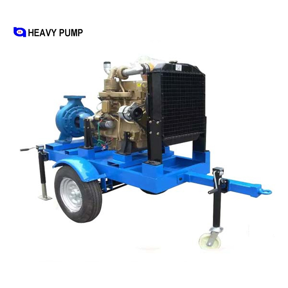
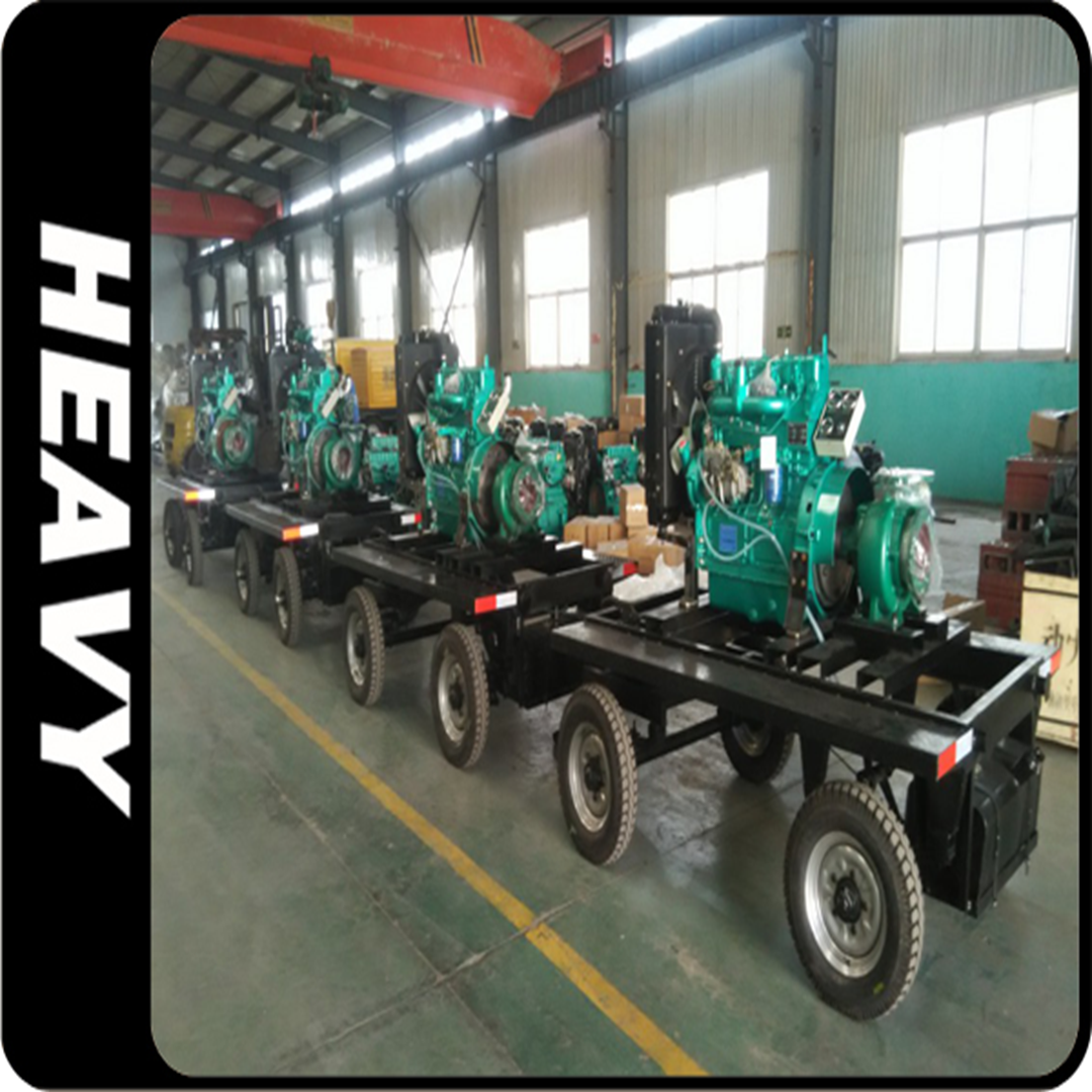
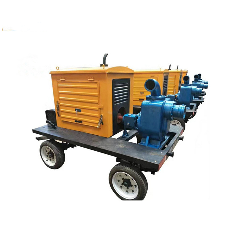
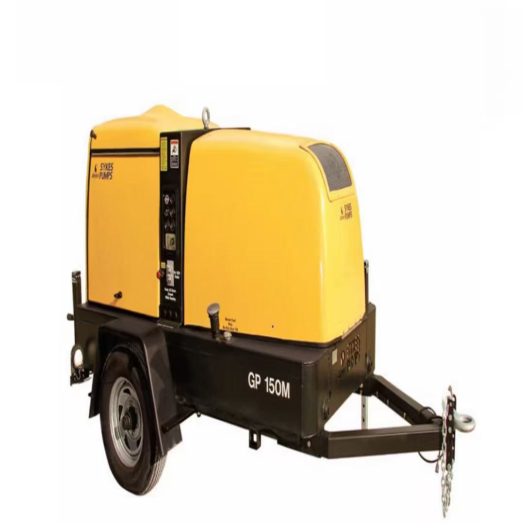
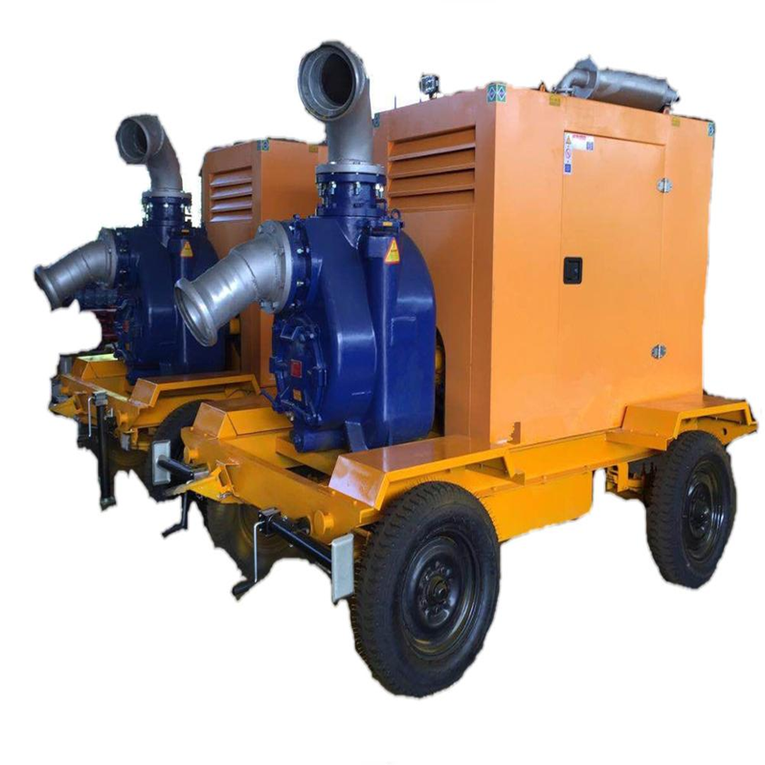
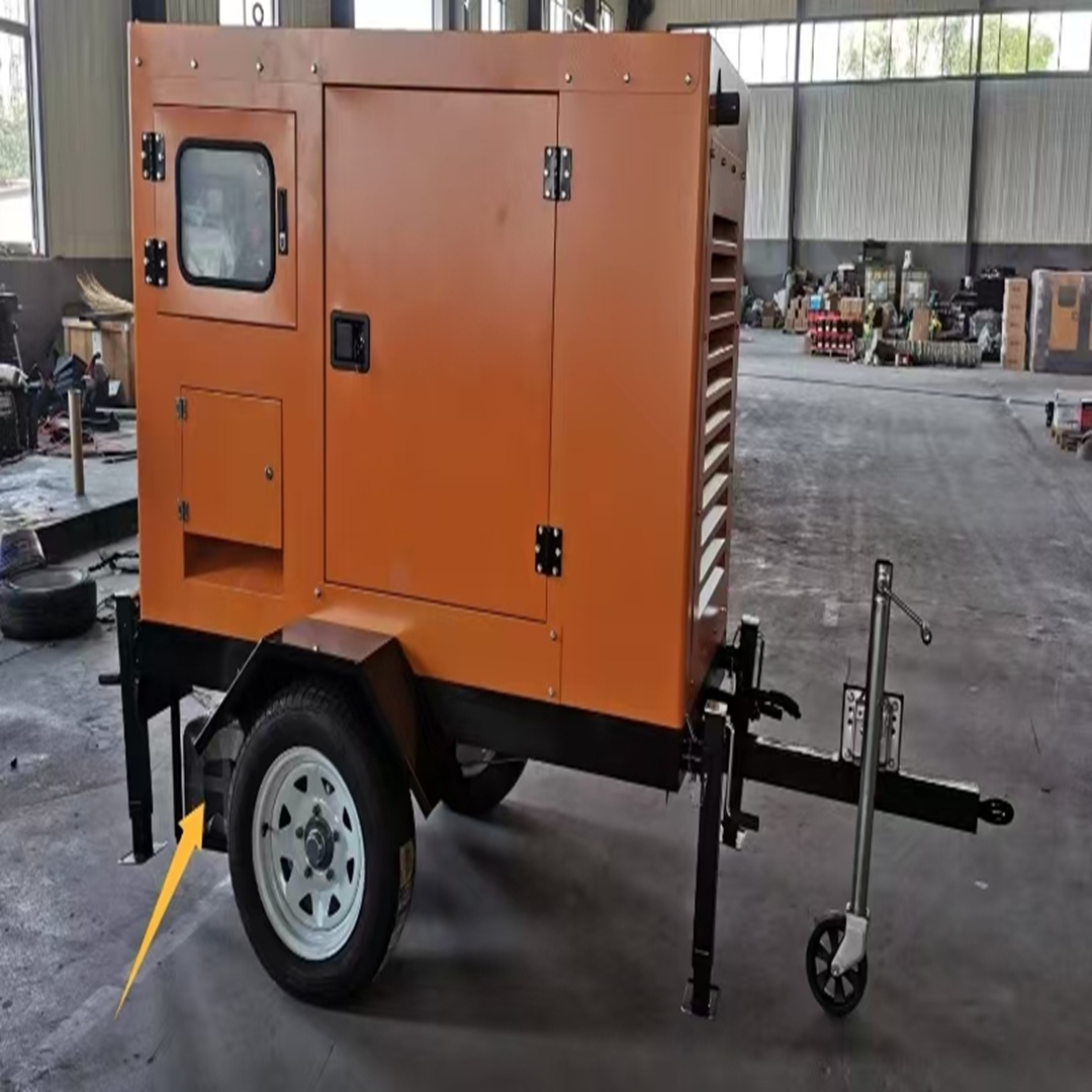
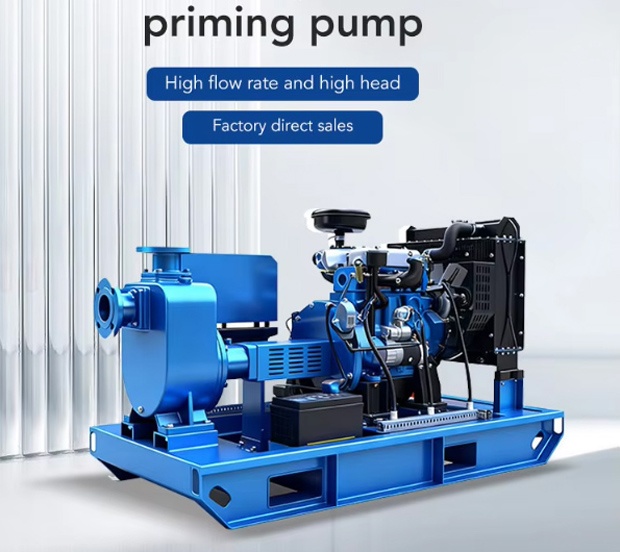
In areas without electricity, diesel engines can power water pumps, creating a mobile diesel-powered pumping unit. This setup not only solves water extraction challenges in off-grid environments but also allows flexible relocation between locations. The diesel-powered pump system proves particularly effective for vast regions with limited power infrastructure, efficiently meeting diverse water supply needs.
-
Product application
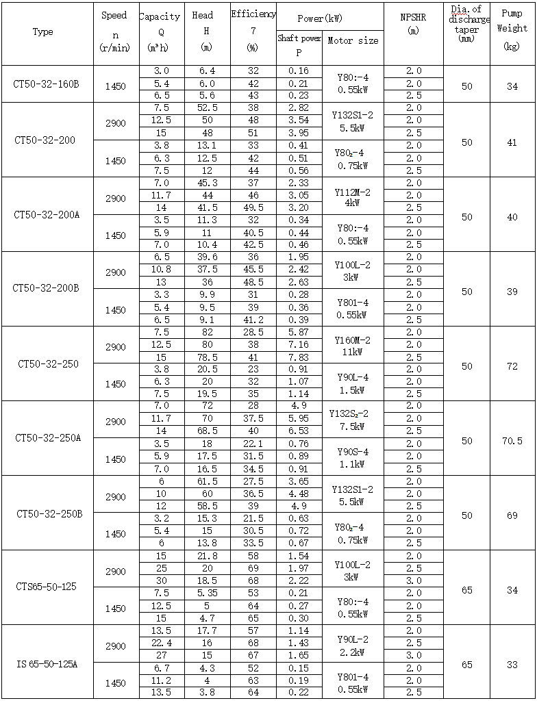
Performance Table
-
Product performance
Brief Diagram Ofstructure
IS125-100-200 Single-stage Single-suction Water Pump with Diesel Engine and 2-Wheel Trailer:
180m³/h flow rate, 50m head, 2900rpm speed.
The 46KW diesel engine drives
the 2-wheel trailer with a muffler.
The pump is directly connected to the diesel engine.
Cost breakdown:
Single-unit single-suction pump: 3,000 yuan
30kW Weifang diesel engine: 4,500 yuan
Belt and pulley connection: 1,200 yuan
wheel trailer: 3,000 yuan
4-wheel trailer: 4,000 yuan
-

 AddressNo.39, Tanan Road, Shijiazhuang, Hebei, China(050024)
 Hotline+86-311-85883441
 Wechat
Wechat